You are here: Home / News / Bare Synthetic Graphite vs. Insulated Laminates: Choosing the Right Construction

Bare Synthetic Graphite vs. Insulated Laminates: Choosing the Right Construction

Views: 0     Author: Site Editor     Publish Time: 2026-11-22      Origin: Site

facebook sharing button
twitter sharing button
line sharing button
wechat sharing button
linkedin sharing button
pinterest sharing button
whatsapp sharing button
sharethis sharing button

Bare synthetic graphite should be selected as a conductive heat-spreading film, not as an electrical-insulation barrier. When the graphite layer may face conductors, pads, shields, screws, or exposed copper, require a separately defined insulation construction and application-specific dielectric review before using it near energized nodes.

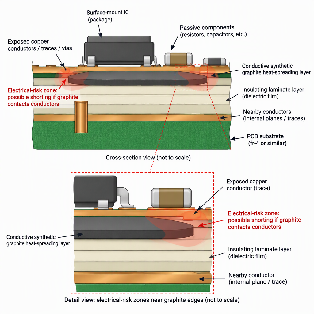
Cross-section concept showing conductive graphite separated from nearby electronics by insulating laminate layers

Bare synthetic graphite is a conductor, not an insulation layer

A bare synthetic graphite sheet can spread heat in compact electronics, but the graphite layer itself should be treated as electrically conductive.

Use bare graphite only when insulation is handled elsewhere

Treat synthetic graphite sheet as a heat-spreading film for electronics; do not assign the graphite layer an insulation role.

Because the bare graphite variants are associated with electrical conductivity values, the bare film should not be assigned the job of separating live circuits.

Use insulation as a separate construction feature

If an insulation function is needed, specify the dielectric layer or laminate construction as the feature to be tested, not the graphite core alone.

For solid insulating materials, electric-strength and surface-breakdown test methods are relevant inputs when the design relies on a dielectric barrier.

The practical rule is simple: do not let the word “graphite” disappear inside the stack-up. If any part of the graphite layer can touch or approach a conductor, review it as a conductive element in the assembly.

When insulated laminate construction is the safer starting point

Choose an insulated synthetic graphite sheet concept when the heat spreader sits near electrical conductors and the design needs a dielectric layer between the graphite and the circuit.

Design condition Bare synthetic graphite Insulated laminate construction
Graphite only spreads heat and is mechanically isolated from conductors Can be considered when the assembly already prevents electrical contact with the conductive graphite layer. May add unnecessary thickness or interfaces if no insulation function is required.
Graphite face is close to copper, pads, shields, batteries, screws, or frames Treat as an electrical-risk item because the bare graphite layer is conductive. Start with a defined dielectric layer and require test conditions that match the intended material stack and environment.
Drawing needs an insulation claim Do not write the claim against the graphite film itself. Tie the claim to the solid insulating material or laminate layer and specify the applicable electric-strength test basis.
Openings, notches, and perimeter edges are near conductors Exposed graphite edges remain a concern. Review surface-breakdown paths and exposed boundaries instead of relying only on face insulation.

Construction options: bare film versus insulated laminate

The construction choice is not a ranking of “better” and “worse”; it is a choice between a conductive heat-spreading film and a heat-spreading stack that also includes a dielectric barrier.

Bare synthetic graphite film

The core functional layer is the graphite film, used to spread heat in electronics.

It is most appropriate when electrical isolation is already handled by the surrounding mechanical and PCB design.

Insulated graphite laminate

The insulation function should be assigned to a specified solid insulating material layer and evaluated under defined test variables.

Where surface breakdown matters, include the laminate surface and exposed boundaries in the review.

Selection field What to define for bare film What to define for insulated laminate
Primary role Heat spreading by the graphite layer. Heat spreading plus a separately defined dielectric interface.
Electrical assumption Assume the graphite layer is conductive. Ask which layer carries the dielectric-strength evidence.
Drawing detail Thickness, outline, adhesive need, and keep-out areas. Layer stack, insulation face, edge condition, hole treatment, and test basis.
Supplier question How will the conductive film be kept away from live conductors? Which laminate layer provides insulation, and how are cut edges controlled?

Edge, cutout, and hole risks engineers should check

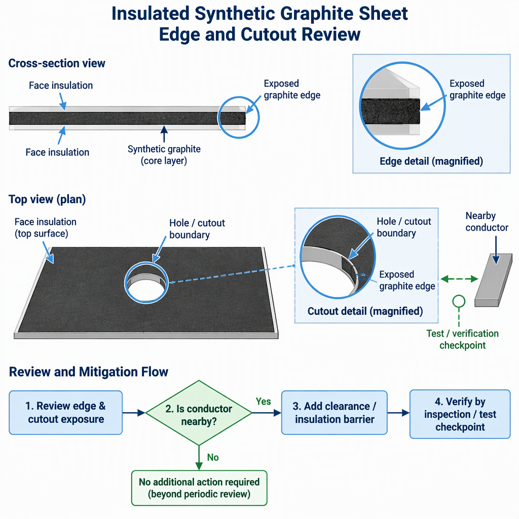
Face insulation alone is not enough if the graphite edge, a punched hole, or a die-cut opening can expose the conductive layer near a conductor.

Decision diagram showing face insulation, exposed graphite edge, cutout boundary, nearby conductor, and verification checkpoint
  • Check the full perimeter for exposed graphite, including tabs, narrow bridges, and hand-applied trimming areas.
  • Check every opening that passes around screws, bosses, shield cans, connectors, pogo pins, or copper features.
  • Review whether the risk path is through the insulating layer, across the surface, or around the cut boundary.
  • Define the test specimen, preparation, electrodes, surrounding medium, and temperature when dielectric-strength data will be used for the decision.
  • Put the required edge treatment, insulation overhang, and inspection criteria on the drawing instead of leaving them to informal interpretation.

Do not copy a face-layer dielectric result into an edge-risk decision without checking whether the surface and cutout geometry are represented by the test method and specimen.

Test methods are evidence inputs, not finished-product approvals

Dielectric-strength test methods can help qualify insulating materials, but they do not by themselves prove that a finished device is electrically safe.

ASTM D149-25 is the active ASTM standard test method for dielectric breakdown voltage and dielectric strength of solid electrical insulating materials at commercial power frequencies.

ASTM’s public scope emphasizes defined test conditions and variables such as voltage application method, specimen preparation, surrounding medium, temperature, and electrodes; it also cautions that results can seldom be used directly to determine dielectric behavior in an actual application.

IEC 60243-1:2013 is an IEC International Standard, edition 3.0, for short-time electric-strength testing of solid insulating materials at power frequencies between 48 Hz and 62 Hz, and its public page notes surface breakdown-voltage methods for solid insulating materials.

Use these standards to frame the material-test question. For equipment compliance, the engineer still needs the applicable end-product safety standard, PCB spacing rules, environmental assumptions, assembly drawing, and supplier documentation.

Engineering checklist before specifying an insulated synthetic graphite sheet

Before sourcing an insulated synthetic graphite sheet, define the electrical-risk case as clearly as the heat-spreading requirement.

Decision item What to ask for Why it matters
Conductive core Confirm where the graphite layer is exposed or enclosed. Bare graphite should be treated as conductive.
Insulating layer Identify the dielectric material, side coverage, and intended contact face. The dielectric-strength question belongs to the solid insulating material and defined specimen.
Edge and opening design Specify perimeter condition, hole treatment, and inspection points. Surface and boundary paths can be part of the electric-strength review.
Test basis Ask for the test method, specimen preparation, electrodes, medium, and temperature. A single dielectric-strength number is not enough without the test conditions.
System approval Map the laminate data to the product safety, PCB, and environmental requirements used by the device team. Material-test evidence does not automatically determine real-application dielectric behavior.
  • Show keep-out zones around exposed graphite and conductive hardware.
  • Call out whether insulation is required on one face, both faces, edges, or openings.
  • Require a drawing-level stack-up rather than relying on a marketing term alone.
  • Ask the supplier to provide separate evidence for heat-spreading performance and electrical-insulation behavior.
  • Review the final die-cut shape, not only the flat sheet material.

Conclusion

Choose bare graphite only when the design needs a conductive heat spreader and electrical isolation is solved elsewhere; choose an insulated laminate when the graphite sheet must sit near conductive features.

  • Do not treat bare synthetic graphite as an insulation layer.
  • Specify dielectric evidence by material, specimen, test condition, and application limit.
  • Check surfaces, edges, holes, and cutouts when the laminate is used near conductors.

FAQ

The most common questions come from assigning the right job to each layer: graphite for heat spreading, dielectric materials for insulation, and the final assembly for safety compliance.

Is bare synthetic graphite electrically insulating?

No. Treat the bare graphite layer as conductive and do not use it as the electrical barrier between live parts.

What is an insulated synthetic graphite sheet?

It is best specified as a heat-spreading graphite layer combined with a separate dielectric construction. Ask the supplier to identify the layer that provides insulation.

Can dielectric-strength data prove that my finished device is safe?

No. Dielectric-strength testing is a material-test input, and ASTM cautions that results can seldom be used directly to determine dielectric behavior in an actual application.

Why do holes and die-cut openings matter?

They can expose the conductive graphite layer or shorten the path to nearby conductors, so the finished shape needs its own electrical-risk review.

Which test standards should I ask about?

For dielectric breakdown of solid electrical insulating materials at commercial power frequencies, ASTM D149-25 is a relevant test-method reference.

For short-time electric strength of solid insulating materials at 48 Hz to 62 Hz, IEC 60243-1:2013 is a relevant IEC reference.

Can I use one datasheet number to select the laminate?

Use the number only with its test conditions, including specimen preparation, voltage application method, electrode setup, medium, and temperature.

What should go on the engineering drawing?

Include the stack-up, insulating side, exposed-edge rules, hole and cutout treatment, keep-out areas, and the test documentation required for the electrical-risk case.

GET IN TOUCH

  No.888, Guangming Road, High-tech Zone, Xinyu, Jiangxi, China
  +86-512-6638 9461
  +86-138 6217 7522

PRODUCT LINKS

QUICK LINKS

Copyright © 2023 Jiangxi Dasen Technology Co., Ltd.