You are here: Home / News / Can Multilayer Synthetic Graphite Replace One Thicker Sheet?
Can Multilayer Synthetic Graphite Replace One Thicker Sheet?
Views: 0 Author: Site Editor Publish Time: 2026-11-14 Origin: Site
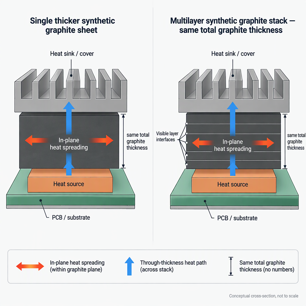
A multilayer synthetic graphite stack should not be approved as a drop-in replacement for one thicker sheet at the same total thickness. Sheet-like graphite and graphene heat spreaders are anisotropic, so in- spreading, through-thickness behavior and assembled-stack characterization all matter; added layer interfaces can also change contact resistance in measurement and assembly contexts.
Can multilayer synthetic graphite replace one thicker sheet?
Yes, but only after the assembled multilayer stack is validated for the actual heat source, mechanical fit and electrical isolation requirements; high in- spreading alone is not enough for approval.
One thicker sheet
A single sheet keeps the graphite path simpler and avoids deliberately adding graphite-to-graphite layer interfaces, while still requiring characterization because graphite heat spreaders can behave differently in- and through thickness.
Multiple thinner layers
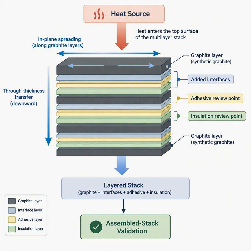
Consider a stack only when form-factor or assembly constraints justify it, because each added layer boundary, adhesive film or insulating film becomes part of the heat path you need to review.
Decision point
One thicker sheet
Multilayer stack
Heat path
Fewer internal layer boundaries, with anisotropic properties still requiring proper characterization.
More boundaries where contact resistance can influence the effective result.
Design freedom
Best used as the baseline when the geometry accepts a single sheet and the test result meets the target.
Worth considering when mechanical layout, routing or assembly handling favors several thin plies, provided the final stack is tested.
Approval risk
Lower stack-complexity risk, but still not approved by nominal in- conductivity alone.
Higher interface-review burden because adhesive, lamination pressure and insulation can affect contact behavior.
What changes when total thickness stays the same?
When total graphite thickness is unchanged, the key change is not just material volume; it is how anisotropic heat spreading, through-thickness transfer and added interfaces combine in the assembled path.
For anisotropic heat-spreading materials, treat sheet-like graphene and graphite materials as potentially high in- and lower through-thickness; characterize anisotropic behavior before approving the thermal solution.
Same-total-thickness check
What to compare
Why it matters
In- spreading
Compare the heat-source footprint, sheet orientation and target spreading area.
The value of graphite heat spreading is often tied to the in- direction, not only to total thickness.
Through-thickness path
Check how heat enters and exits the sheet or stack.
A design with strong in- spreading can still be limited by the through-thickness route.
Layer boundaries
Count every graphite-to-adhesive, adhesive-to-graphite and insulation boundary.
Account for interface contact resistance because it can materially affect measured thermal-conductivity results in steady-state measurement contexts.
Where do interfaces, adhesive and insulation change the result?
Interfaces, adhesive and insulation can change the result wherever they interrupt the heat path, change contact quality or add electrical-isolation requirements that were not present in a single bare graphite sheet.
Map each contact boundary in the proposed stack before comparing it with a single thicker sheet.
Separate in- spreading expectations from through-thickness transfer expectations in the design review.
Evaluate adhesive as a thermal-path element, not only as a handling or bonding aid.
Check whether any insulating film, coating or liner adds a new interface near the heat source or heat sink.
Ask the supplier for assembled-stack test data that matches the direction of heat flow used in your design.
How should you validate a multilayer design?
Test the multilayer design as an assembled thermal component, not as a sum of individual graphite layers, because anisotropic properties and interface effects both influence the practical result.
Define the heat-flow direction. State whether the design goal is lateral spreading, through-thickness transfer to a chassis or a combination of both.
Build the real stack-up. Include graphite plies, adhesive, insulation, liners and the intended contact surfaces rather than testing only loose graphite layers.
Test the single-sheet baseline. Use one thicker sheet as the control if it fits the mechanical envelope.
Test the multilayer candidate. Keep pressure, fixture contact, surface preparation and assembly method consistent enough to make the comparison meaningful.
Review the result against the application. Approve the stack only after the thermal, mechanical and isolation results match the actual device requirement.
Record in- and through-thickness assumptions separately.
Document contact surfaces and fixture pressure used in testing.
Include adhesive and insulation layers in the sample build.
Compare temperature distribution, not only a nominal material-property line.
When is multilayer safer than a single sheet, and when is it not?
A multilayer stack is safer to consider when geometry or assembly constraints justify the added interfaces; a single thicker sheet should remain the baseline when it fits and meets the thermal requirement with fewer stack variables.
Design scenario
Prefer starting point
Buyer check
Flat area, simple contact path
One thicker sheet
Confirm anisotropic characterization and compare against the device thermal target.
Tight routing, local folding need or staged assembly
Multilayer candidate
Check whether added interfaces and adhesive layers offset the layout benefit.
Electrical isolation required near the heat path
Architecture-dependent
Review the insulating layer as both an electrical barrier and a thermal-path element.
Approval based only on a supplier’s in- conductivity value
Neither approved yet
Request assembled-stack characterization in the relevant heat-flow direction.
Conclusion
Choose multilayer synthetic graphite only when the complete stack proves itself against the single-sheet baseline in the same application geometry.
Use the single thicker sheet as the simpler baseline when it fits the design.
Treat every added interface, adhesive and insulation layer as part of the thermal path.
Validate the assembled stack in the heat-flow direction your product actually uses.
The practical decision is not “more layers versus fewer layers.” It is whether the multilayer construction delivers the required spreading, contact behavior, isolation and assembly fit after the whole stack is tested.
FAQs about multilayer synthetic graphite heat spreading
Use these questions to screen a multilayer graphite proposal before releasing it into a thermal design.
Can multiple thinner graphite layers help when bend or assembly fit matters?
They can be worth considering when the mechanical layout makes one thicker sheet difficult to place, but the stack still needs assembled validation because graphite heat spreaders are anisotropic.
Does adhesive automatically improve heat transfer between graphite layers?
No. Adhesive may improve handling or contact consistency in a design, but it also introduces another material and interface into the thermal path.
Is high in- thermal conductivity enough to approve the stack?
No. In- behavior is only one part of an anisotropic heat-spreading design; through-thickness behavior and the assembled contact path also need review.
Should engineers test the assembled stack rather than only individual layers?
Yes. Testing only individual sheets can miss the effect of layer boundaries, fixture contact and adhesive or insulation interfaces in the final construction.
How many interfaces are too many?
There is no universal safe count from the cited measurement literature. Count each interface and require application-specific testing before accepting the multilayer design.
When should one thicker sheet remain the baseline?
Keep it as the baseline when it fits the package, reaches the target in validation and avoids stack complexity that the multilayer option has not justified.