


Synthetic graphite sheet spreads heat very effectively in its own , and in a body-worn device that is exactly the behaviour you have to prove: the sheet also conducts electricity, and it can carry heat straight toward the wearer. Before design freeze, validate measured skin-side temperature against a written contact-time criterion, electrical isolation provided by a separate dielectric layer, and assembly reliability of the bonded stack — on the assembled product, not from a datasheet.
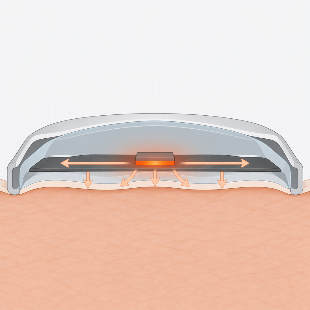
- Ask for grade-specific in- thermal conductivity: listed grades range from roughly 900–1100 W/m·K up to 1600–1800 W/m·K depending on thickness, measured by laser flash at a third-party laboratory.
- The same grade table shows electrical conductivity of the order of 106 to 107 S/m, so the sheet is a conductor and never the isolation barrier.
- Skin-side temperature, dielectric strength and adhesion are properties of the assembled stack; a material certificate cannot stand in for those measurements.
- Contact-burn criteria are derived from contact time, surface configuration and an acceptable injury level, so there is no single universally safe surface temperature.
How do you validate touch temperature when a graphite sheet moves heat toward the skin?
Measure the skin-facing surface of the assembled device at steady state and in the worst-case power mode, then compare the result with an acceptance criterion you wrote before testing, based on how long the product can touch skin and how much exposure you accept. A graphite sheet changes the internal heat path; it does not by itself decide the outer surface temperature.
- Set the criterion before you build. The ASTM C1055-20 guide derives acceptable surface conditions from estimated contact time, surface configuration and an acceptable injury level, and contrasts a short industrial contact with a much longer consumer contact. It applies to passive heated surfaces in contact with skin and does not declare any surface temperature safe.
- Build a representative assembly: production enclosure, the same carrier film, adhesive and compression, and the real electrical load including charging and radio transmit bursts.
- Instrument the contact surface rather than the heat source, using fine thermocouples or an infrared-transparent window at the locations that touch skin, and log the run until the temperature stops rising.
- Run the worst case: highest intended ambient temperature plus the highest sustained power mode, held against a thermally representative surface or skin phantom at the intended contact pressure.
- Report a margin, not just a pass. Record measured temperature, criterion, build configuration and conditions so a later enclosure or material change can be re-evaluated rather than re-argued.
Is synthetic graphite sheet an electrical insulator in a wearable assembly?
No. Published electrical conductivity for synthetic graphite sheet sits in the 106 to 107 S/m range, which is a conductor, so isolation has to come from a separate dielectric layer — carrier film, coating or encapsulated gap — and its strength must be measured on the finished stack.
The distinction matters when you choose a test method. ASTM D257-14(2021)e1 covers DC resistance and conductance of insulating materials, states that measured values depend on electrification time, applied voltage, temperature and humidity, and is not suitable for moderately conductive materials; the standard names a separate method for those.
| Check | Bare graphite sheet | Graphite laminated behind a dielectric film |
|---|---|---|
| Electrical behaviour | Conductive, in the order of 106 to 107 S/m. | The film provides the barrier; the graphite beneath it stays conductive. |
| Property to measure | Sheet resistance or conductivity, if you need the value at all. | Dielectric breakdown voltage and dielectric strength of the film as assembled. |
| Applicable method | Not an insulation-resistance measurement; those methods are written for insulating materials. | A dielectric breakdown test at commercial power frequency, with electrode geometry, conditioning, medium and failure criterion fixed by the specifying document. |
| What a pass establishes | That the sheet met its stated conductivity. | That this specimen, in this fixture, met the stated criterion. |
| What it does not establish | Anything about isolation. | Anything about leakage current, creepage, cut-edge pinholes or device-level electrical safety. |
Which assembly and reliability checks belong in a graphite stack qualification?
Qualify the stack rather than the sheet: adhesion between graphite, adhesive and carrier film; edge and crease damage from handling; bending at the tightest radius your design uses; and stability after the temperature and humidity cycling the product will actually see.
- Rank adhesion on the real substrates with a tape method such as ASTM D3359-23, which rates a relatively ductile film on a metallic substrate on a 0–5 scale. It is insensitive to all but large differences and depends on the angle and rate at which the operator removes the tape, so use it to compare lots and processes rather than as a pass/fail specification.
- Bend and crease at the design radius. Published repeated bending figures for the sheet describe the sheet alone; your device bends at its own radius with adhesive and film bonded to it.
- Cycle the bonded stack through the temperature and humidity range of the intended use, looking for delamination, bubbling, adhesive squeeze-out and a change in thermal resistance.
- Audit handling and assembly damage: cut-edge quality, burrs, folding during pick-and-place, and any rework step that creases the sheet.
- Check the compression budget: sheet thickness tolerance plus adhesive plus film against the gap the enclosure actually provides.
- Adhesion result recorded as a rank, together with tape type, cut pattern, substrate, conditioning and operator.
- Flex test at the tightest radius in the design and at the temperature extremes of the operating range, not only at room temperature.
- Incoming thickness measured against the grade tolerance, and measured again after compression in the assembly.
- Visual acceptance criteria for creases, edge chips and delamination agreed before the first build.
- Rework and repair rules agreed with manufacturing, because re-laminating a creased sheet is not equivalent to a first build.
What can a passing ASTM test result tell you about the finished wearable?
It tells you that a specimen met a stated criterion inside a defined method. It does not prove the device, because the methods themselves state that their results can seldom be applied directly to an actual application. Use them to compare candidate materials and to control incoming lots, then measure the assembled product.
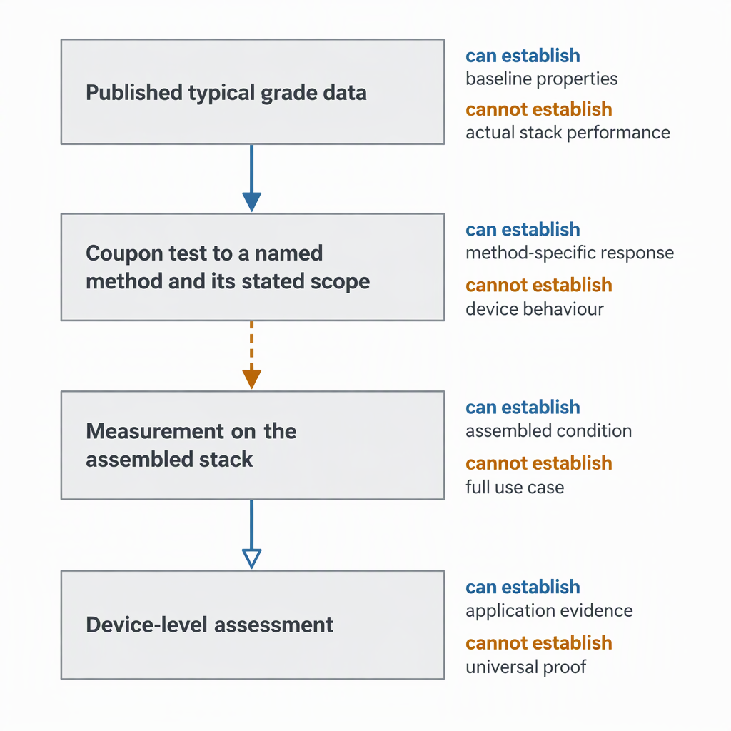
Two scope statements decide how far a coupon result travels.
ASTM D149-25, which measures dielectric breakdown of solid insulating materials at commercial power frequencies; its scope states that results can seldom be used directly to determine dielectric behaviour in an actual application, and it is not intended for intrinsic dielectric strength or thermal failure under electrical stress.
ASTM D5470-17(2024) measures steady-state thermal impedance of thermally conductive electrical insulation materials under idealized parallel heat flow at an average specimen temperature; do not apply those impedances directly to practical applications where heat does not flow uniformly.
A thin graphite spreader rarely sees uniform parallel heat flow, so treat a coupon impedance as a screening number rather than a design allowable.
Where does biological evaluation sit relative to graphite thermal validation?
Biological evaluation belongs to the finished device and its body-contact category, not to the graphite sheet. FDA's final guidance on the use of ISO 10993-1 describes a risk-based biological evaluation inside a risk-management process: contact category and contact duration decide whether testing is needed, and the guidance carries specific recommendations for devices that contact only intact skin.
Which evidence should a graphite supplier provide for a medical device project?
Request grade-specific data for the exact construction you will receive — thickness and tolerance, in- thermal conductivity with its test method, electrical conductivity, density, operating temperature range with any film excluded, and bending limits — plus the reports behind those numbers and a lot-to-lot control statement. Treat a published table as typical values until that package exists.
| Item | What it decides for a wearable | A weak answer looks like |
|---|---|---|
| Thickness and tolerance | The gap and compression budget inside the enclosure | A nominal thickness with no tolerance for the grade you would order |
| In- thermal conductivity and its test method | Whether the spreading is worth the stack height | A range with no thickness dependence and no indication of how it was measured |
| Electrical conductivity or resistance | Confirms that isolation must be designed in separately | Wording that implies the sheet is an insulator |
| Operating temperature range | Cycling limits for the assembly | A heat-resistance figure that silently includes or excludes a PET film |
| Carrier film and adhesive data | Dielectric and adhesion behaviour of the real stack | A film named without thickness, dielectric strength or adhesive data |
| Lot control and incoming inspection | Whether production stays inside the qualified window | No control plan and no inspection fields |
| Quality management system | Supplier qualification, not product performance | A certificate shown without its scope or validity date |
A medical-device application listing shows where a material family is marketed, not device-specific validation, test or approval data; treat it as context, not qualification evidence.
A supplier's website may state a founding year, headcount, workshop area, annual capacity and an ISO 9001 quality management system. Those are company statements about a management system, not evidence of the thermal, dielectric or adhesion behaviour of a delivered sheet; ask for the certificate and its scope.
- Grade datasheet with thickness, tolerance, density, heat capacity and operating range.
- A thermal conductivity report naming the method and testing laboratory.
- Electrical conductivity or sheet resistance values for the specific grade.
- Construction drawing of the laminate: film type and thickness, adhesive, total stack thickness.
- Dielectric data for the film as supplied, if the order includes one.
- Certificate-of-analysis fields and the sampling plan behind them.
- Quality-system certificate with scope, plus an engineering contact for change notification.
- Written confirmation that material data is not device-level approval and does not replace your own stack testing.
What is the minimum validation set before committing to a graphite heat spreader?
Four items: a measured skin-side temperature for the assembled device against a written contact-time criterion; a dielectric-strength result for the isolation layer on your real stack; adhesion, flex and cycling results for the bonded construction; and a supplier data package that matches the grades you would actually order. Anything less leaves the device, not the material, unproven.
Work through them in order.
- Touch temperature: criterion set from contact time and acceptable exposure, measured on the worst-case build.
- Isolation: dielectric strength of the barrier layer measured within the method's own scope, on the assembled geometry.
- Assembly: adhesion ranking, bending at the design radius, and thermal and humidity cycling of the bonded stack.
- Material: grade data with methods, and confirmation that the sheet is conductive so isolation is designed in rather than assumed.
Biological evaluation, device-level electrical-safety testing and regulatory submission run alongside this work on the finished device; none of the four items above substitutes for them.
Frequently asked questions about synthetic graphite in wearable medical electronics
These are the questions that most often decide whether a synthetic graphite heat spreader moves from a concept sketch into a qualification plan.
Is a thermally conductive graphite sheet also an electrical insulator?
No. Published electrical conductivity for synthetic graphite sheet is of the order of 106 to 107 S/m, so the sheet conducts. Conductivity and electrical insulation are separate properties, and a material can excel at the first while offering none of the second. The isolation comes from a dielectric layer, and that layer is what you qualify.
Is there a single 'safe' surface temperature for skin contact?
No. ASTM C1055-20 derives acceptable surface conditions from estimated contact time, surface configuration and an acceptable injury level, and explicitly declines to name a universally safe surface temperature. A device worn for hours needs a different criterion from a surface touched for seconds, so write the criterion from your own risk assessment and measure against it.
Which test method measures the dielectric strength of the insulation layer around a graphite heat spreader?
A dielectric breakdown test at commercial power frequency is the usual starting point for a solid insulating layer, and ASTM D149-25 is the publisher's current edition. It requires a specifying document that fixes electrode geometry, specimen conditioning, surrounding medium and failure criterion, and its scope states that results can seldom be transferred directly to an application.
Resistance methods are a different family. ASTM D257 is written for insulating materials and is not intended for moderately conductive materials, which is what a graphite sheet is, so do not use it as evidence that the graphite insulates anything.
What in- thermal conductivity can I expect, and how was that number produced?
Published grades list in- values from about 900–1100 W/m·K up to 1600–1800 W/m·K depending on thickness, and the supplier states the values were measured by laser flash at a third-party laboratory. Those are material-level figures for the sheet: they help you compare grades and estimate spreading, but they do not predict the surface temperature of an assembled wearable.
How thin are these sheets, and does thickness change the thermal performance?
Listed grades run from 17 µm to 100 µm with stated tolerances, alongside density of 1.4–2.0 g/cm³, heat capacity of 0.85 J/g/K and an operating range of −40 to 400 °C. Thickness is not thermally neutral: the highest in- values are published for the thinnest grades and the 70–100 µm grades sit lower, so choose thickness against your available gap and the spreading you need rather than assuming thinner is always better.
Will a graphite sheet survive repeated bending in a body-worn product?
The published table gives repeated bending of 20,000 to 50,000 cycles at 180° around an R5 radius for listed grades, which is a useful indication of the sheet's own flexibility. It is a material-level figure at one radius and one angle; a bonded stack in a wrist-worn product bends at its own radius with adhesive and film attached, so flex the assembly at that radius and at the temperature extremes before you rely on the number.


